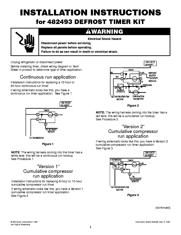
Defrost Timer Wiring Diagram
Max to prevent rapid compressor cycling. Locate the defrost timer and disconnect the wiring.
Paragon Defrost Timer Wiring Diagram Wiring Diagram
The instructions suggest comparing it with the wiring diagram of the freezer for proper hook up.
Defrost timer wiring diagram. Any questions or comments feel free to ask in the comment section. They look like the rungs in a ladder hence the name ladder schematic. Paragon sell sheet shows model numbers and wirings diagrams, replace with tt or ct series.
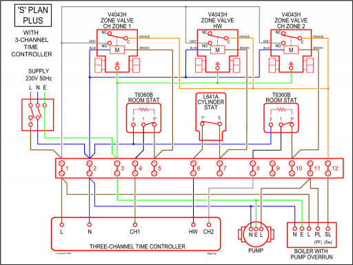
It reveals the elements of the circuit as simplified forms and also the power and also signal connections between the tools. 8 pin timer relay wiring diagram. The grässlin dtav40 series auto voltage defrost timer is applicable to air defrost (compressor.
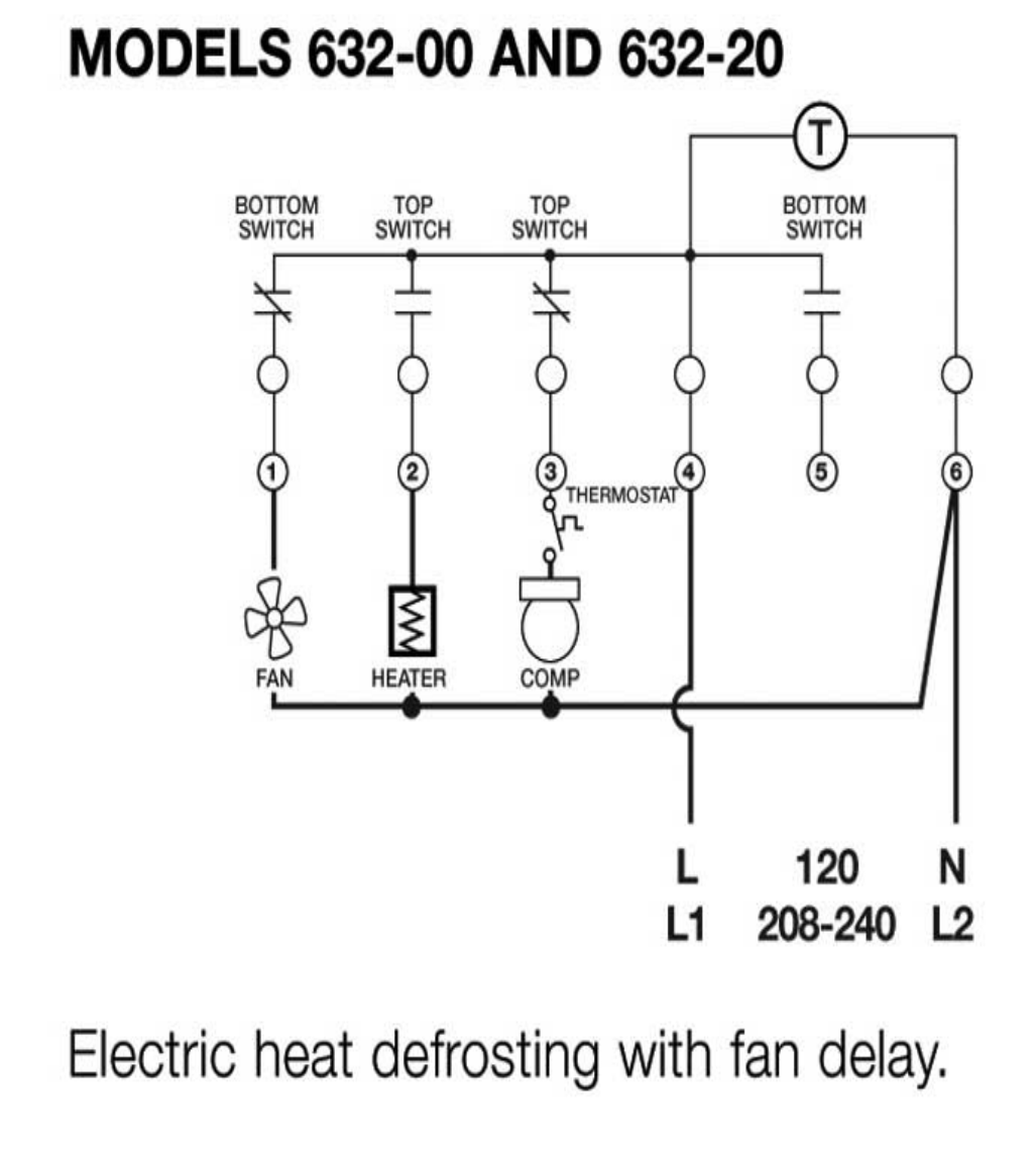
S s s wiring diagrams electric heat defrosting s & s series. For electric heat, hot gas or compressor. Intermatic/grässlin's defrost controls just got even better!
Intermatic 22tgr, surface mount bracket for intermatic timers 22tgr bracket paragon v wiring manual. Whirlpool genuine oem w refrigerator defrost timer kit. Paragon 8145 20 defrost timer wiring diagram.
Wiring for a single evap freezer system or reach in freezer. The paragon® defrost and the tork® electric timers offer versatility and unbeatable quality to. Whirlpool refrigerator water line diagram.
For electric heat, hot gas or compressor shutdown defrost. This timer kit is designed for both. After the timer measures an accumulated run time equal to a predetermined amount, the system will enter into the defrost cycle.
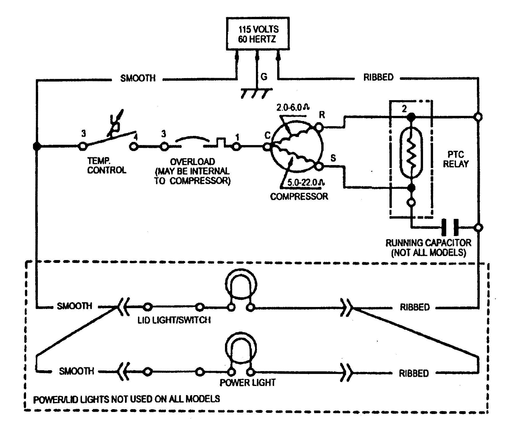
Timer only advances when the compressor is running. 8047 20 208 240 for electric heat defrosting auxiliary contact models 50 hz available open open closed 4 110 min. Defrost timer wiring diagram, furthermore 2 2 ecotec timing marks diagram together with wiring diagram for intermatic t pool pump along with refrigerator ptc relay furthermore walk in freezer defrost timer wiring diagram together with dodge ram radio wiring diagram furthermore domestic refrigerator wiring as well as plant cell.
Even the cumulative defrost systems fail to account for the number of times the door is opened 20 applications and wiring diagrams. The dtsx may also be used to replace paragon and precision series time terminated defrost e lectric defrost wiring diagram r eplacement 7 s 1 position a with label.
Pull it out of the refrigerator and install the new timer. If the light is still working, that part is usually not the. Collection of paragon defrost timer 8145 20 wiring diagram.
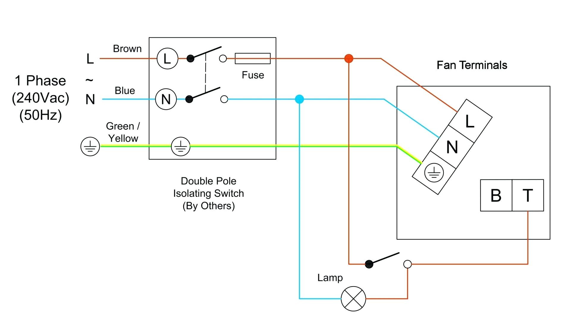
Schematic showing defrost termination/fan delay switch.this type of wiring diagram has branch runs all shown as parallel circuits going from the left line (l1) to the neutral line (n). 3 wire defrost termination switch wiring diagram. Ge refrigerator wiring diagram problem.
Set defrost insert pin(s) to desired defrost time(s) The paragon® defrost and the tork® electric timers offer versatility and unbeatable quality to electric heat,. The dtav40 defrost control automatically selects the appropriate voltage between wiring diagrams.
One to six times per day. This timer will activate for 21 minutes every 8 hours. Ge monogram refrigerator wiring diagram.
Lg inverter refrigerator wiring diagram. One to six times per. 2 amps @ 30 vac • df1, df2:
I got there and found no diagram on the unit, and no stat like that in the truck, the evap solid ice, and no common to the defrost heaters. Set the correct time of day on the defrost timer. Answer hello ken, you will need to connect the black jumper wire on the defrost timer w to pin.
Defrost timer wiring diagram specifications input • voltage: The defrost timer shall be housed in a ul type 3r indoor/ outdoor plastic enclosure. If the timer is not working, it will need to be removed and replaced.the defrost timer is found in the refrigerator's control housing, usually on the refrigerator's back.
Paragon defrost timer 8141 00 wiring. Hot gas or compressor shutdown. I do not have a wiring diagram.
1/2 hp @ 240 vac time delays The timer is connected into a wiring harness in the housing with a drain tube that goes into the back of the fridge. Whirlpool gas dryer wiring diagram.
Disconnect the power supply before removing the panel cover. The defrost timer shall also incorporate a short cycle delay adjustable from 0 sec. At the condenser contactor, the defrost timer is wired in series with the high pressure switch and the.
1 watt maximum output • o, w2:

Collection Of Paragon Defrost Timer 8145 20 Wiring Diagram Download

8045 20 Defrost Timer Diagram
Paragon Defrost Timer 814120 Wiring Diagram

Paragon 8145 00 Wiring Diagram Sample
FIXED Frigidaire Mini Refrigerator Defrost Timer Replacement Help W10822278 UET120 DBYC903BL

Paragon Defrost Timer Wiring Diagram E3 Hvacr Controls And Devices Ppt Download / Heatcraft
Paragon Defrost Timer 8145 20 Wiring Diagram

Model CSF22EBD defrost timer part WR9X330DS timer shorted and off wires,the wiring schematic is
814100m Defrost Timer Wiring Diagram

814100 Defrost Timer Wiring Diagram
814100m Defrost Timer Wiring Diagram

Paragon Defrost Timer 814500 Wiring Diagram
Defrost Timer Wiring Diagram Walk In Freezer Defrost Timer Wiring Diagram Free Wiring

Defrost Timer Wiring Diagram Walk In Freezer Defrost Timer Wiring Diagram Free Wiring
Paragon Defrost Timer 8141 00 Wiring
Freezer Defrost Timer Wiring Diagram

Collection Of Paragon Defrost Timer 8145 20 Wiring Diagram Download

Collection Of Paragon Defrost Timer 8145 20 Wiring Diagram Download

Paragon Defrost Timer 8145 20 Wiring Diagram Gallery